Fire alarm design is the work of deciding what a fire detection and fire alarm system has to do in a particular building, and then laying out the detectors, manual call points, sounders, visual alarm devices, control equipment, power supplies and cables that will do it. In the UK, for non-domestic premises, that work is normally carried out to BS 5839-1. The current edition is BS 5839-1:2025.
This guide walks through the fire alarm system design process stage by stage, with the BS 5839-1:2025 clause behind each step. The clause figures are summarised in our own words from the standard. They are a guide for designers and do not replace reading the standard itself. At the end of each stage we explain where Fire3D can take the repetitive work off your hands. Fire3D can run a fully automated fire alarm design from a floor plan PDF.
What fire alarm system design covers
BS 5839-1:2025 gives recommendations for the design, installation, commissioning and maintenance of fire detection and fire alarm systems in and around buildings other than domestic premises (clause 1). It does not say whether a building needs a system at all. The introduction explains that the need is normally decided by the enforcing authority and/or by the fire risk assessment, and that the standard assumes that decision has already been made. Domestic premises are covered by a different part, BS 5839-6.
The introduction also makes a point that shapes every design: a principal purpose of the system is to support the building’s fire evacuation strategy. The design should fit the evacuation procedure, not the other way round. So before any device goes on a drawing, the designer needs to know how the building will be evacuated: simultaneously, in phases, or with staff alarms first.
Section 2 of the standard, “Design considerations”, runs from clause 7 to clause 28. It covers the relationship between category and protected areas, zoning, alarm zones, communication with the fire and rescue service, audible and visual alarms, manual call points, detector selection and spacing, control equipment, networked systems, power supplies, cables, radio-linked systems, EMC and earthing. Section 3 adds the design measures for limiting false alarms.
Who is responsible for the design
Clause 5 of BS 5839-1:2025 is about exchanging information and defining responsibilities. It recommends consultations before and during the design stage between the user or purchaser, consultants, the designer and, where relevant, the enforcing authority and the property insurer (5.1 and 5.2). Before an order is placed, responsibility for design, installation, commissioning and handover should each be clearly defined and documented (5.6). The responsibility for providing the zone plan should be agreed and documented too (5.7).
The category of system is a related question. Clause 4 describes the categories but does not say which one a given building needs. FIA guidance on selecting and specifying a fire alarm category under BS 5839-1 (Version 2, January 2026) places the responsibility for choosing the category with the fire safety specialist, not with the system designer or contractor. If the designer has not been told the category, clause 4.2 asks them to make clear to the purchaser which category their design would conform to. See the FIA’s guidance on BS 5839-1 fire alarm categories.
The fire alarm design process, step by step
1. Brief, evacuation strategy and category
Collect the floor plans, the fire risk assessment or fire strategy, the evacuation procedure and the agreed category. BS 5839-1:2025 clause 4 sets out the categories:
- Category M: manual systems, with no automatic fire detectors.
- Category L1 to L5: automatic systems for the protection of life, from L1 (throughout the building) through L2 and L3 down to L4 (circulation areas of escape routes) and L5 (designed for a specific fire safety objective).
- Category P1 and P2: automatic systems for the protection of property, throughout the building (P1) or in defined parts (P2).
Any variations from the standard should be agreed between the interested parties and listed on the relevant certificate (clause 6).
2. Fire detection zones
Clause 12 sets the zoning rules. In summary, if the building’s total floor area is over 300 m², each zone should be limited to a single storey (12.1b). A zone that contains only manual call points should not exceed 2,000 m², or 10,000 m² for a zone that is mainly a single open-plan area such as an uncompartmented warehouse (12.2). A zone with non-addressable automatic detectors should not exceed 2,000 m², and the search distance should not exceed 60 m (12.3). For addressable detectors, the 60 m search distance can be relaxed where the panel clearly displays the location of the first detector to operate in a way that would let firefighters who don’t know the building find the fire (12.4). Enclosed stairwells, lift wells and similar flue-like structures should be zoned separately (12.3c).
3. Detector selection and spacing
Clause 20 covers choosing detector types, and Annex D gives informative guidance on selection. Clause 21 covers siting and spacing. Under flat ceilings, no point in a protected area should be more than 7.5 m horizontally from the nearest smoke detector, or 5.3 m from the nearest heat detector (21.2.1). In corridors no more than 2 m wide, that works out at intervals of 15 m for smoke detectors and 10.6 m for heat detectors (Note 2 to 21.2.1). Pitched roofs, voids, beams, obstructions, honeycomb ceilings and ceiling height limits (21.8, Table 3) all have their own rules. Our guide to fire alarm detector spacing and coverage goes into more detail.
4. Manual call points
Clause 19 says no one should need to travel more than 45 m to reach the nearest manual call point, measured along the route a person would actually take (19.5). If the final layout is not known at design stage, a 30 m straight-line distance is used until fit-out, and 45 m applies afterwards. Where equipment or activities create a high fire hazard, such as kitchens or paint spraying, a call point should be sited close by (19.6). See manual call point locations.
5. Sounders
For Category M and L systems (other than hospitals and residential care premises), clause 15.1.1 recommends a sound pressure level of at least 65 dB(A) throughout accessible areas, with 60 dB(A) acceptable in stairways, enclosures of up to about 60 m² and specific points of limited extent. Where people need to be woken, the level should be at least 75 dB(A) at the bedhead. No normally accessible point should exceed 120 dB(A). Where background noise is above 60 dB(A), the alarm should be 5 dB(A) above it (15.1.3). The system should have at least two sounders (15.1.10). Our guide to sounder coverage calculation works through the numbers.
6. Visual alarm devices
Clause 16 recommends visual alarm signals where ambient noise exceeds 90 dB(A) and where hearing protection is likely to be worn (16.1). VADs should be sufficient in number and distribution to be readily visible from all normally accessible locations in the area they serve (16.2). Clause 5.5 asks the designer to find out from the user or purchaser whether VADs are to be included at all. See VAD coverage calculation to EN 54-23.
7. Control equipment and the zone plan
Clause 22 covers the control and indicating equipment (CIE). Next to the indicating equipment there should be a diagrammatic representation of the building showing at least the entrances, the main circulation areas and the division into zones (22.2.5). That can be an illuminated mimic, a VDU with suitable back-up, or a printed and correctly orientated zone plan. BS 5839-1:2025 defines a zone plan in clause 3.76. Fire3D’s fire alarm zone plan software produces that printed plan.
8. Power supplies and standby batteries
The standby supply should be a rechargeable battery with an automatic charger (24.3.1). For a Category M or L system in most buildings, the battery should run the system for at least 24 h and then still give an “Evacuate” signal in all alarm zones for at least 30 min. With an automatically started standby generator, the figure is at least 6 h plus 30 min (24.3.5). Category P systems have their own durations.
Battery capacity is calculated to Annex E. For valve-regulated lead acid batteries, the minimum capacity is 1.25 × (T1 × I1 + D × I2 × T2), where T1 and I1 are the standby period and load, T2 and I2 the alarm period and load, and D a de-rating factor. If Cmin/20 is at least I2, D can be taken as 1. If it is less, D comes from the battery manufacturer’s data or is taken as 1.75. If the result doesn’t match a battery size, the next size up is used (E.1.3).
Illustrative example only (not from a real job): with a standby load of 0.2 A for 24 h and an alarm load of 1.0 A for 0.5 h, D = 1 gives 1.25 × (4.8 + 0.5) = 6.6 Ah. Cmin/20 is then about 0.33 A, which is less than the 1.0 A alarm load, so without manufacturer data D = 1.75. That gives 1.25 × (4.8 + 0.875) ≈ 7.1 Ah, and the next available battery size up would be used.
9. Cables and circuit integrity
Clause 11 covers fault monitoring and system integrity. For example, a fault on one circuit should not affect any other circuit (11.2.1), and a single fault on a sounder circuit should still leave at least one sounder working, normally near the CIE (11.2.9). Clause 25 covers cables. Standard fire-resisting cable is sufficient for most systems (25.3 and 25.5). Enhanced fire-resisting cable is generally needed in cases such as unsprinklered buildings over 30 m tall or with four or more evacuation phases (25.4). Conductors should be at least 1 mm² (25.7), and fire alarm cables should be a single common colour, preferably red (25.9).
10. False alarm limitation
Section 3 (clauses 29 to 33) treats limiting false alarms as part of the design. Clause 32 sets out the design process, and clause 33 covers measures such as siting manual call points, choosing and siting automatic detectors, and choosing the system type.
11. Documentation and certification
Clause 38 lists the documentation to be handed to the user or purchaser. It includes the design, installation and commissioning certificates, an operation and maintenance manual, as-fitted drawings, a cause-and-effect matrix or description, a logbook and a record of agreed variations. Clause 39 asks for a separate certificate for each of design, installation and commissioning, and Annex G gives model certificates. A design certificate is the formal end of the design stage. Fire3D’s fire alarm specification software produces the design specification and device schedules. See fire alarm as-fitted drawings
How Fire3D automates fire alarm design
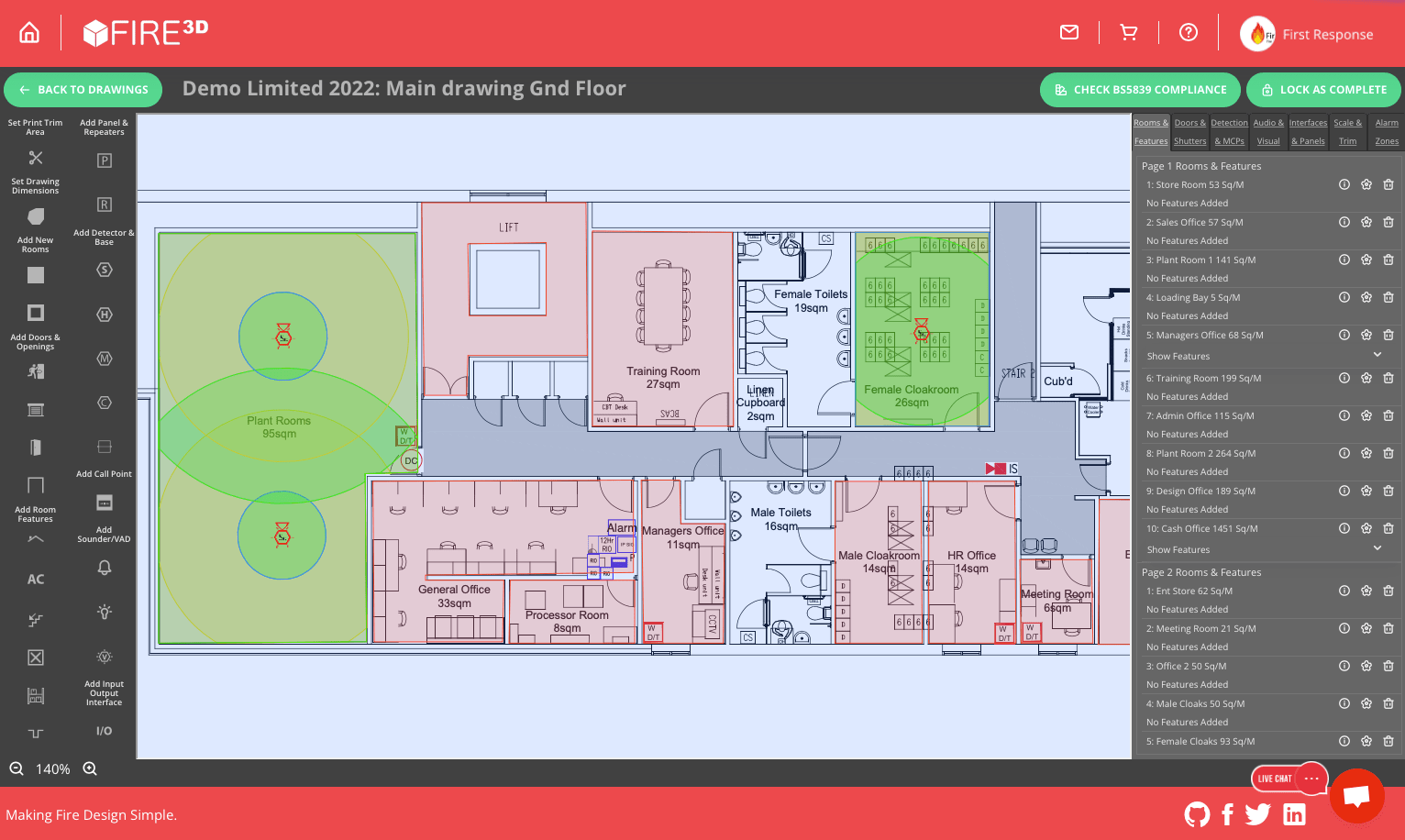
Most of the steps above follow fixed rules applied to a floor plan, and Fire3D automates them. You upload a floor plan PDF. Fire3D detects the scale and crop area, then detects rooms, doors, room uses and escape routes. You choose a suite of devices to use, and Fire3D auto-fills the design with detector heads, detector bases, sounders, VADs and manual call points from that suite to satisfy BS 5839-1. Other parts can be added manually.
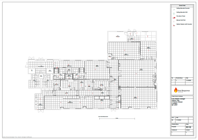
The crop is placed into a new engineering drawing with your logo, in an AutoCAD style. All output is vector PDF, so detail holds at any zoom level. See automated fire alarm design software
| Design stage | BS 5839-1:2025 | What Fire3D does |
|---|---|---|
| Read the floor plan | Section 2 generally | Detects scale, crop area, rooms, doors, room uses and escape routes from the PDF |
| Detectors | Clauses 20 and 21 | Auto-fills detector heads and bases from your chosen device suite, and checks detector coverage |
| Manual call points | Clause 19 | Auto-fills MCPs and checks 45 m travel distance |
| Sounders and VADs | Clauses 15 and 16 | Auto-fills sounders and VADs and runs sounder and VAD coverage checks |
| Zoning | Clause 12 | Checks the 60 m zone search distance |
| Zone plan | Clauses 3.76 and 22.2.5 | Produces a printed zone plan as vector PDF |
| Documents | Clauses 38 and 39 | Generates the specification, device schedules and quotes, plus as-fitted drawings with as-wired cable routes, types and sizes |
| Category, variations, sign-off | Clauses 4, 5 and 6 | These stay with the competent people responsible |
The coverage checks are described on the fire alarm coverage checks page. Once the devices are placed, the as-fitted designer pulls them through from the automated design, so the as-fitted drawings start from the same layout. Fire3D also includes an AI emergency lighting designer that uses the same room, door, room-type and escape-route detection. See emergency lighting design software
The designer still owns the design
Automation makes the layout faster, but it doesn’t make anyone less responsible for it. A competent person still has to review the auto-filled design, add the parts that can’t be detected from a floor plan, apply the agreed category and any variations, and sign the design certificate. A layout auto-filled to the BS 5839-1 rules is a strong starting point. It is not a certificate of compliance.
Plans and pricing
Automated design and the emergency lighting designer are included in both paid plans. Growing is £49.99 per month, or £499.90 a year billed annually. Unlimited is £99.99 per month, or £999.90 a year billed annually. There is a 30-day free trial and no credit card is needed. Full limits are on the Fire3D pricing page. If you are comparing tools, the homepage covers Fire3D as fire alarm design software.
Frequently asked questions
What British Standard covers fire alarm design?
For non-domestic premises in the UK, fire alarm design is normally carried out to BS 5839-1. The current edition is BS 5839-1:2025. It covers design, installation, commissioning and maintenance. Domestic premises are covered by BS 5839-6.
What are the main steps in fire alarm system design?
Agree the brief, evacuation strategy and category. Then zone the building, select and space detectors, place manual call points, design sounder and VAD coverage, site the control equipment and zone plan, size the standby power, choose cables, design out false alarms, and produce the documentation and design certificate.
Who chooses the fire alarm category?
BS 5839-1:2025 clause 4 describes the categories but does not choose one for a building. FIA guidance (Version 2, January 2026) places that choice with the fire safety specialist, not the system designer or contractor. If no category has been given, clause 4.2 asks the designer to tell the purchaser which category their design meets.
How far apart should smoke detectors be?
Under flat ceilings, BS 5839-1:2025 clause 21.2.1 recommends that no point is more than 7.5 m horizontally from the nearest smoke detector, or 5.3 m from the nearest heat detector. Other rules apply to pitched roofs, beams, voids and high ceilings.
How long should fire alarm standby batteries last?
For most Category M and L systems, BS 5839-1:2025 clause 24.3.5 asks for at least 24 h of standby followed by at least 30 min of “Evacuate” signal in all alarm zones, or 6 h plus 30 min where an automatically started standby generator serves the system. Capacity is calculated using Annex E.
Can software design a fire alarm system automatically?
Fire3D can. From a floor plan PDF it detects the scale, crop area, rooms, doors, room uses and escape routes, then auto-fills detector heads, bases, sounders, VADs and manual call points from your chosen device suite to satisfy BS 5839-1. Other parts can be added manually, and a competent designer still reviews and signs off the design.
Do I need AutoCAD to design a fire alarm system?
No. Fire3D places the cropped floor plan into a new engineering drawing with your logo, in an AutoCAD style, and all output is vector PDF.
Related pages and guides
Try an automated fire alarm design on your own floor plan
Start a 30-day free trial, with no credit card, upload a floor plan PDF and see the design auto-filled to the BS 5839-1 rules.