A fire alarm wiring diagram shows how the devices in a fire detection and fire alarm system are wired together: which devices are linked by which cable, the route each cable takes, and the cable type and size. Installers use the wiring diagram to wire the system as intended. Service engineers use it years later to trace a cable, find a fault or extend the system.
In Fire3D, the wiring diagram is the as-wired output of the as-fitted designer. It shows the cable links between devices, with the cable routes and the cable types and sizes, drawn on the same plan as the devices from your automated design. Like all Fire3D output, it is a vector PDF in an engineering drawing with your logo.
This page explains what a fire alarm wiring diagram needs to show, which parts of BS 5839-1:2025 affect the wiring, and how Fire3D produces the diagram. Clause references are summarised in our own words and do not replace the standard.
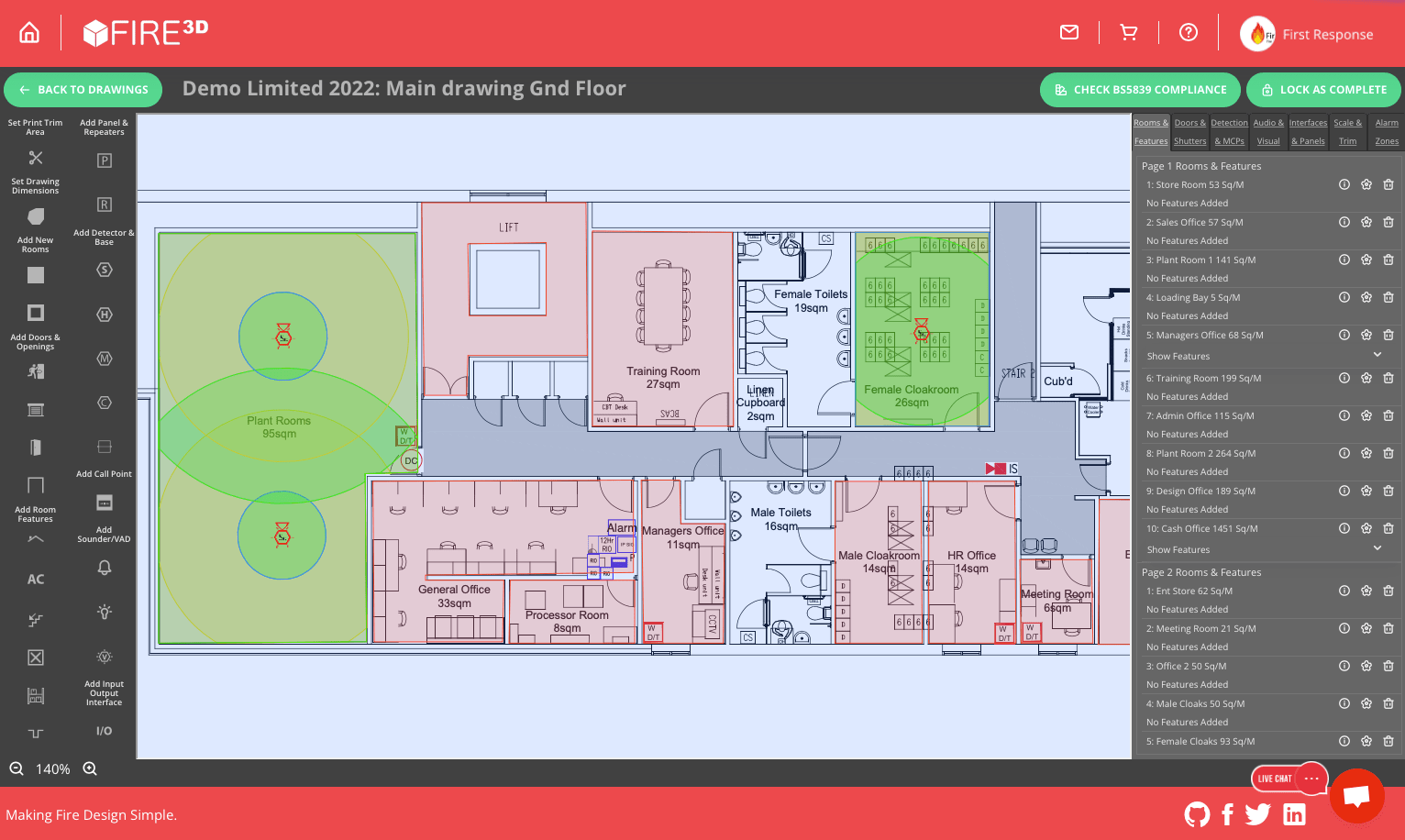
What a fire alarm wiring diagram should show
- Cable links between devices. Which detectors, call points, sounders and VADs are connected to each other and back to the panel.
- Cable routes. The path each cable takes through the building, so someone else can find it later.
- Cable types and sizes. For example, whether a run uses standard or enhanced fire-resisting cable, and the conductor size.
Fire3D’s wiring diagrams show all three.
Why routes matter: BS 5839-1:2025 clause 38.1c
Clause 38.1c asks for as-fitted drawings that show, among other things, the type, sizes and actual routes of cables. Note 3 adds that the routes should be a reasonable representation of the path followed, so a competent person can locate a cable for a fault, modification or extension. It warns that a simple schematic showing only the sequence in which devices are wired is unlikely to be enough, except on small, simple systems.
That is why Fire3D draws the wiring on the real floor plan, with routes, types and sizes, as part of the as-fitted designer, rather than as a separate sequence-only sketch. The same drawing can then be issued as the as-fitted record for handover. See fire alarm as-fitted and as-wired drawings
BS 5839-1:2025 rules that shape the wiring
Circuit integrity (clause 11)
Clause 11.2 sets out how faults should be contained. A fault on one circuit containing call points, detectors or alarm devices should not affect any other circuit (11.2.1). A single open-circuit or short-circuit fault on a detector circuit should not disable protection over more than 2,000 m², or on more than one floor plus a maximum of five devices on the floors immediately above and below (11.2.2). Two simultaneous faults should not disable protection over more than 10,000 m² (11.2.3).
For sounders, a single open-circuit or short-circuit fault on a sounder circuit should still leave at least one sounder, normally near the CIE, sounding correctly during a fire alarm (11.2.9). The standard gives two example arrangements: a separate, independent sounder circuit feeding a single sounder near the panel (Figure 1, radial sounder circuits), or a ring circuit with short-circuit isolators either side of a sounder at the start (or end) of the loop (Figure 2, ring circuits such as addressable loops). Other arrangements are not ruled out.
Cable types and sizes (clause 25)
Clause 25 covers cables, wiring and interconnections. Electrical characteristics such as voltage drop and current-carrying capacity should follow BS 7671 (25.1). For most systems, standard fire-resisting cable is sufficient: 30 min survival, class PH 30 (25.3 and 25.5). Enhanced fire-resisting cable gives 120 min survival, class PH 120 (25.6). It should generally be used in situations such as unsprinklered buildings over 30 m in height or with evacuation in four or more phases (25.4). Conductors should be at least 1 mm² (25.7). Fire alarm cables and the mains supply should be one common colour, not used for general electrical services, with red preferred (25.9). Recording the cable type and size on the wiring diagram shows which of these applies to each run.
Installation and wiring tests (clauses 35 and 36)
Section 4 covers installation. Clause 35 deals with installation practice and workmanship, including the screen continuity examples in Figures 25 and 26. Clause 36 covers inspecting and testing the wiring. A wiring diagram that shows each cable link and route makes both jobs easier to plan and record.
How Fire3D produces the wiring diagram
1. Design
Upload a floor plan PDF. Fire3D detects the scale and crop area, rooms, doors, room uses and escape routes, then auto-fills detector heads, bases, sounders, VADs and manual call points from your chosen device suite to satisfy BS 5839-1.
2. As-fitted designer
The as-fitted designer pulls the devices in from the automated design. Edit it to match any changes made on site.
3. As-wired cabling
Add the cable links between devices, with the cable routes and the cable types and sizes.
4. Issue
Issue the wiring diagram as a vector PDF engineering drawing with your logo.
Because the wiring sits in the as-fitted designer, the devices and the cabling stay on one drawing. You don’t have to keep a separate wiring diagram in step with the as-fitted drawing.
Wiring diagrams for BAFE SP203-1 work
BAFE SP203-1 (Version 8.0.1) treats the recommendations of BS 5839-1 as normative requirements (clause 4.2), and asks certificated organisations to keep comprehensive project records that show changes made during the project (clause 10.1.2). Fire3D’s as-fitted output, including the as-wired cable links, routes, types and sizes, meets the as-fitted documentation requirements of BS 5839-1 and BAFE SP203-1. Fire3D itself is not BAFE certified. Certification applies to your organisation. See BAFE SP203-1 audit documents.
Plans and pricing
Fire3D has two paid plans. Growing is £49.99 per month (£499.90 a year billed annually). Unlimited is £99.99 per month (£999.90 a year billed annually). Both include automated design and the emergency lighting designer. There is a 30-day free trial and no credit card is needed. See Fire3D pricing.
Frequently asked questions
Does Fire3D produce fire alarm wiring diagrams?
Yes. Fire3D’s wiring diagrams are the as-wired output of its as-fitted designer. They show the cable links between devices, with the cable routes and the cable types and sizes, as a vector PDF.
What should a fire alarm wiring diagram show?
The cable links between devices and the panel, the route each cable takes, and the cable type and size. BS 5839-1:2025 clause 38.1c asks for cable types, sizes and actual routes, and Note 3 says a simple wiring-sequence schematic is unlikely to be enough except on small, simple systems.
Can I change the wiring diagram if the installation changes on site?
Yes. The wiring is part of the as-fitted designer, and as-fitted drawings can be edited to match changes made on site.
What does BS 5839-1 say about sounder circuit wiring?
Clause 11.2.9 says a single open-circuit or short-circuit fault on a sounder circuit should still leave at least one sounder working, normally near the CIE. Examples include a separate single-sounder circuit next to the panel, or a ring circuit with short-circuit isolators either side of the first (or last) sounder.
What cable should be used for a fire alarm system?
BS 5839-1:2025 clause 25 recommends standard fire-resisting cable (PH 30) for most systems, and enhanced fire-resisting cable (PH 120) in situations such as tall or phased-evacuation unsprinklered buildings. Conductors should be at least 1 mm², and fire alarm cables should be one common colour, red preferred.
Related pages and guides
Draw your next wiring diagram in Fire3D
Start a 30-day free trial, with no credit card, design from a floor plan PDF, then add the cable links, routes and sizes in the as-fitted designer.