
Visual alarm devices (VADs) are the flashing beacons that warn people who may not hear the sounders. Working out how many you need and where they go depends on the device category, the size and layout of the room, and how bright the room already is. This guide explains the method and works through two examples.
BS 5839-1:2025 deals with VADs in clause 16 (and clause 17 for people who are Deaf or have a hearing impairment), and clause 10.16 says VADs should conform to BS EN 54-23. Importantly, the standard does not set out coverage volumes or ambient light correction factors. For those it points to LPCB/FIA CoP 0001. The multiplication factors below match LPCB/FIA CoP 0001 clause 4.6.9.3 Table 1 (ceiling/wall × direct/indirect view, ambient bands up to 800 lux). CoP 0001’s worked example also multiplies the mounting-height rating by the same factor. Where a lux value sits on a band edge (for example exactly 400 lux), the printed ranges overlap; use the more onerous (lower) factor unless the manufacturer says otherwise. Above 600 lux, CoP 0001 prefers direct viewing (4.6.9.4a); above 800 lux it calls for photometric design with specialist input (4.6.9.4b). Still check your device datasheet before relying on any figure.
When Are VADs Needed?
Clause 16.1 says visual alarm signals should be provided in areas where ambient noise exceeds 90 dB(A) and in other areas where hearing protection is likely to be used. These areas are normally identified by a sign (Figure 7 in the standard). The commentary adds that VADs supplement audible alarms where sounders are likely to be ineffective, and that they are sometimes the sole initial warning to staff in places such as studios, cinemas, theatres and hospital operating theatres, where an audible warning is undesirable.
They can also be used to warn people who are Deaf or have a hearing impairment (clause 17). The need for, and extent of, VADs is specific to the premises. Often they are only needed in a few areas, such as toilets or plant rooms where a person might be alone. In public buildings where people sleep, such as hotels, the commentary to clause 17 refers to tactile devices, with or without associated visual alarm devices.
What Clause 16 Asks For
- Visibility: sufficient in number and distribution to be readily visible from all normally accessible locations in the area they serve, under normal ambient lighting levels (clause 16.2).
- Colour and consistency: clearly distinguishable from other visual signals, white or red or both, and consistent throughout the premises (clause 16.3).
- Flash rate and synchronisation: a flash rate of 3 Hz or less from a single device is unlikely to cause seizures in people with photosensitive epilepsy, but several unsynchronised devices in an open area can appear to flash faster, so synchronisation might be necessary. Red is more likely to cause problems than white (note to clause 16.3).
- Intensity: enough to attract attention without causing glare (clause 16.4).
- Mounting: fixed in the ceiling or wall position and orientation specified by the manufacturer, with a mounting height of not less than 2.1 m (clause 16.5).
EN 54-23 Categories In Brief
The category descriptions below come from EN 54-23 manufacturer literature, not from BS 5839-1. Devices are certified to a coverage volume in which a minimum illumination (given as 0.4 lux in that literature) is achieved. Each device is certified to one or more categories:
- C-x-y (ceiling) - x is the maximum mounting height in metres (typically 3, 6 or 9 m) and y is the diameter of the cylinder of coverage. A C-3-7.5 device covers a cylinder 7.5 m across when mounted at up to 3 m.
- W-x-y (wall) - x is the maximum mounting height (given as at least 2.4 m) and y is the width of a square coverage volume. A W-2.4-7.5 device covers a 7.5 m by 7.5 m square, 2.4 m high.
- O (open) - the manufacturer declares the coverage shape, mounting position and height limits. Always read the datasheet, as there is no standard shape.
A quick conversion for ceiling devices: a cylinder of diameter y covers a square room of side about y ÷ 1.414. A C-3-7.5 device covers a square of about 5.3 m.
BS 5839-1 notes that CoP 0001 allows two approaches: an engineered, application-specific solution for complex situations, and a predetermined approach for rooms of simple geometry, specified size and commonly encountered ambient light levels. Category C or W devices are normally used with the predetermined approach. Category O devices are only intended for application-specific designs where the manufacturer’s data and your calculations show compliance with CoP 0001.
Ambient Light: The Brighter The Room, The Smaller The Coverage
In a bright room a flash is harder to notice, so coverage has to shrink. In a dark room it can grow. Manufacturer literature citing CoP 0001 gives multiplication factors that you apply to the rated coverage distance, based on the ambient light level and whether the person has a direct or indirect view of the device.
Ambient light means artificial light and daylight combined. Use the highest level likely to occur, including daylight from windows. Rooms with large windows can be far brighter than their artificial lighting suggests. Blinds may reduce daylight, and you can measure with a lux meter or take lighting design figures.
The factors published in that literature (ceiling direct / ceiling indirect / wall direct / wall indirect) are commonly given as:
- Below 100 lux: 2.8 / 1.3 / 5.2 / 1.8
- 100 to 200 lux: 2.4 / 1.2 / 4.4 / 1.7
- 200 to 300 lux: 1.9 / 1.0 / 3.2 / 1.4
- 300 to 400 lux: 1.4 / 0.8 / 2.3 / 1.2
- 400 to 500 lux: 1.1 / 0.6 / 1.8 / 1.0
- 500 to 600 lux: 0.9 / 0.5 / 1.3 / 0.9
- 600 to 700 lux: 0.7 / 0.4 / 1.0 / 0.7
- 700 to 800 lux: 0.5 / 0.3 / 0.7 / 0.6
CoP 0001 Table 1 stops at 800 lux; above that, clause 4.6.9.4b says consult the VAD manufacturer or a lighting specialist and use photometric calculations. The same factor also applies to the mounting-height rating, which matters, as the examples show.
Direct And Indirect View
Direct view means everyone in the area can see the device itself. Indirect view means they would only see light reflected from walls or other surfaces. Direct view is better and allows a larger coverage distance. If you rely on indirect view, the reflecting surfaces must be inside the coverage volume.
Worked Example 1 - Ceiling VAD In An Office
Room 8 m by 6 m, ceiling 2.7 m, VAD rated C-3-7.5, everyone has direct view.
- Half the room diagonal is 5 m (the diagonal is 10 m), so a single central device must cover a cylinder 10 m across.
- Ambient 350 lux (artificial light only): ceiling direct factor 1.4. Coverage = 7.5 × 1.4 = 10.5 m, which is enough. Height rating = 3 × 1.4 = 4.2 m, which is above 2.7 m. One VAD at the centre works.
- Ambient 650 lux (bright daylight through windows): factor 0.7. Coverage = 7.5 × 0.7 = 5.25 m, and the height rating falls to 3 × 0.7 = 2.1 m. That is below the 2.7 m ceiling, so this device cannot be used as rated. You would need a device with a higher rating, or to control daylight, and probably more devices.
Worked Example 2 - Wall VAD In A Meeting Room
Room 9 m by 6 m, VAD rated W-2.4-7.5 mounted at 2.4 m, direct view.
- Ambient 450 lux: wall direct factor 1.8. The square becomes 7.5 × 1.8 = 13.5 m, which contains the whole 9 m by 6 m room. Height rating 2.4 × 1.8 = 4.3 m, which is fine. One device is enough.
- Ambient 650 lux (daylight peak): wall direct factor 1.0. The square stays at 7.5 m, which is shorter than the 9 m length, so two devices are needed, one covering each half of the room.
Points To Remember
- Check the VAD category and rating on the datasheet. Do not assume every device is the same.
- Check obstructions. Partitions, shelving and pillars can block direct view, and clause 16.2 requires the device to be readily visible from all normally accessible locations in the area.
- The standard sets a minimum mounting height of 2.1 m (clause 16.5). Check that any factor-adjusted height rating still allows the height you can actually fit.
- Synchronise VADs in the same area where possible (note to clause 16.3).
- Record the lux values and assumptions you used so the design can be reviewed.
This article is a guide for designers and does not guarantee compliance with BS 5839-1, EN 54-23, CoP 0001 or any legal requirement.
Want us to calculate everything & show you visually on your floor plan?
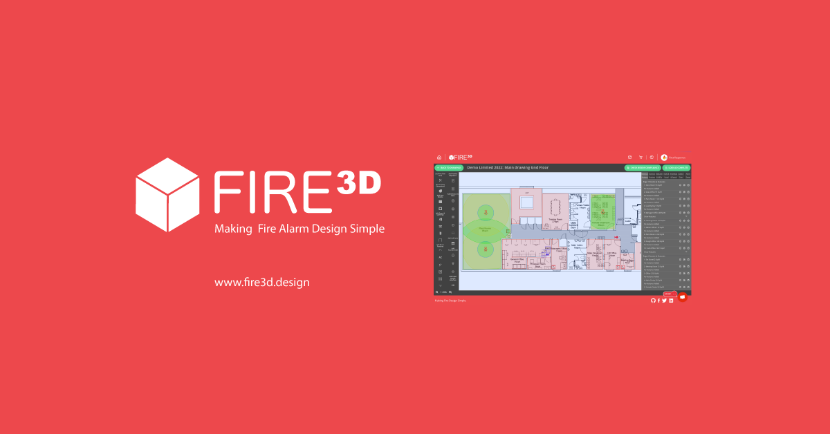
Fire3D checks ambient light levels, daylight compensation, direct and indirect classifications and obstructions to line of sight. It also checks mounting heights, light output shapes and Open class EN 54 VAD classifications, and shows you the coverage visually on your floor plan.
Try out Fire3D for yourself
Click the 'Click to see what Fire3D can do' button above, or start your free trial using the button below and start designing today.